WIRE TONGS
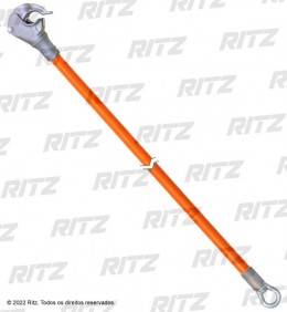
It is generally used to hold and move energized conductors from their original positions. It allows electricians to service crossarms, insulators, removing and placement of poles and hardware, as well as mounting new components, such as lightning arresters, in overhead lines.
This stick is usually operated in pairs or with other complementary tools such as: saddles; clamps; blocks. All are specially designed for quick and safe service.
Constructed with RITZGLAS® tube and aluminum alloy fittings (for better mechanical strength and lightness ratio), the steel swivel eye has a bearing for smooth and perfect rotation.
The varying wire tong jaw opening allows the conductor to be firmly and securely fixed by rotating the bar until the jaw is fully closed.

| Catalog Reference | Ø (mm) | Insulating Length (m) | Total Length (m) | Conductor Ø (mm) | Rated Work Capacity (traction) | Storage (optional) | Approx. Weight | |||
| Mín. | Máx. | daN | lb | kg | lb | |||||
| RH4645-6 | 38 | 1,74 | 1,99 | 4,10 | 57,00 | 340 | 750 | FLV18339-2 | z | 7,28 |
| RH4645-8 | 38 | 2,35 | 2,60 | 340 | 750 | FLV18339-3 | 3,80 | 8,38 | ||
| RH4645-10 | 38 | 2,95 | 3,20 | 340 | 750 | FLV18339-4 | 4,20 | 9,26 | ||
| RH4646-6 | 51 | 1,72 | 2,07 | 454 | 1000 | FLV18339-2 | 4,60 | 10,14 | ||
| RH4646-8 | 51 | 2,31 | 2,58 | 454 | 1000 | FLV18339-3 | 5,30 | 11,68 | ||
| RH4646-10 | 51 | 2,94 | 3,20 | 454 | 1000 | FLV18339-4 | 6,00 | 13,23 | ||
| RH4646-12 | 51 | 3,60 | 3,87 | 454 | 1000 | FLV18339-5 | 7,50 | 16,53 | ||
| RH4647-8 | 64 | 2,29 | 2,61 | 567 | 1250 | FLV18339-3 | 7,30 | 16,09 | ||
| RH4647-10 | 64 | 2,90 | 3,21 | 567 | 1250 | FLV18339-4 | 8,40 | 18,52 | ||
| RH4647-12 | 64 | 3,45 | 3,77 | 567 | 1250 | FLV18339-5 | 9,40 | 20,72 | ||
| RH4647-14 | 64 | 4,12 | 4,44 | 567 | 1250 | FLV18339-14 | 10,40 | 22,93 | ||
| RH4647-16* | 64 | 4,74 | 5,06 | 567 | 1250 | FLV18339-3 | 13,90 | 30,64 | ||
| RC400-0171 | 76 | 3,45 | 3,78 | 680 | 1500 | FLV18339-5 | 12,70 | 28,00 | ||
| RC400-0172 | 76 | 4,21 | 4,54 | 680 | 1500 | FLV18339-14 | 14,90 | 32,85 | ||
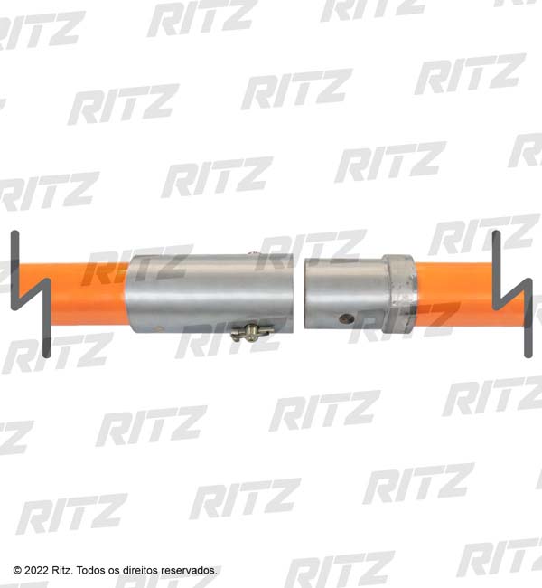
 | The RH4647-16 is spliced wire tong, making it easy to carry. The connection between the two parts is made through a metal splice, of galvanized and fixed steel, with steel pin and pin type cotter pin. |
The diagrams show correct orientation of the use of the wire tongs through the four most used configurations and their workloads.
The electrician must strictly observe the safety distances when using the hot line poles, according to their recommended voltages in the table at the beginning of this catalog.
Fig. 1 - Wire tong with saddle, wire tong blocks clamp, and conductor pulling blocks.
Fig. 2 - Wire tongs with saddles, wire tong band, and conductor pulling block.

| Figure Nº | RITZGLAS® Pole Dimensions Ø (mm) / Length (m) | Support Type | Max. Workload (per Conductor) | Maximum Conductor Size and Span (m) | |||||
| ACSR | Copper | ||||||||
| A | B | daN | lb | Size | Span | Size | Span | ||
| 1 | 51 x 3,55 | 38 x 2,96 | Pole saddle and lift saddle | 125 | 276 | 4/0 | 213 | 4/0 | 91 |
| 64 x 3,51 | 215 | 474 | 366 | 152 | |||||
| 2 | 51 x 3,55 | 38 x 2,96 | Pole saddle and lift saddle | 125 | 276 | 4/0 | 213 | 4/0 | 91 |
| 64 x 3,51 | 215 | 474 | 366 | 152 | |||||
* Based on a fully horizontal wire tong. The lower the upper saddle is placed, below the conductor's level, the higher the tension on pole “A” will be, so the load it can support will be lower
Fig. 3 - Wire tongs, lift saddle, tourniquet pull pole and block used to pull heavy conductors.
Fig. 4 - Set for lifting the three phases where all three conductors are raised simultaneously.

| Figure Nº | RITZGLAS® Pole Dimensions Ø (mm) / Length (m) | Support Type | Max. Workload (per Conductor) | Maximum Conductor Size and Span (m) | ||||||
| CAA | Copper | |||||||||
| A | B | C | daN | lb | Size | Span | Size | Span | ||
| 3 | 51 x 3,55 | 38 | Sela Elevação | 160 | 353 | 4/0 | 259 | 4/0 | 114 | |
| 64 x 3,51 | 454 | 397,5 | 397,5 | 350 | 250 | 259 | ||||
| 4 | 64 x 3,51 | 51 x 2,33 | 51 x 2,33 | Selas para Poste | 102 | 225* | 4/0 | 168 | 4/0 | 70 |
* With maximum lift of 1.52m above the saddle and maximum unbalance of 102 daN/225 lb on one side.
WARNING
WORKLOADS - For the correct selection of tools, the loading information of the structure must be used. When these values cannot be obtained, the whole work structure must be analyzed before the load is applied.
When calculations are not possible (e.g. when a pole is slightly larger than its adjacent pole) just consider the total weight of the adjacent spans as the maximum workload. This does not apply to structures installed at high points, which requires special analysis for load determination.
If the workload is higher than indicated in the table (for a specified pole), use two wire tongs with double lift saddle or use a larger Ø wire tong.
