SPECIFICATIONS - TEMPORARY GROUNDING
An effective electrical connection equipment with intentional low impedance grounding, designed to ensure and maintain equipotential bonding during interventions in the electrical installation, protecting workers from accidental energization.
A proper specification of the temporary grounding set (ATR) is the first principle to ensure efficiency and safety in performing de-energized line work if the system is accidentally energized. Such specification must match the characteristics of the electrical installation where the Temporary Grounding Set will be installed.
CAREFULLY read the following basic requirements for the correct specification of the Temporary Grounding Set to ensure electrician safety.
For the specification of the ATR, the following characteristics of the electrical installations must be known before using it:
a. Installation type and voltage level:
- Overhead network or line (kV);
- Substation (kV);
- Secondary Network (LV) with bare or shielded cable;
- Underground network (kV);
b. Maximum short-circuit current;
c. Protection system actuation time;
d. Structure Type:
- Metal;
- Concrete;
- Wood;
e. Phase-to-phase and phase-to-ground distances;
f. Phase and ground conductor sections where the ATR will be installed.
Maintenance on powered off overhead networks is, at first glance, an apparently safe condition to carry out the work. However, they may be mistakenly energized by several common factors:
- Operational errors;
- Accidental contact with other live circuits;
- Voltages induced by adjacent lines;
- Lightning discharges, even if distant from the workplace;
- Third-party power sources.
Unfortunately, the factors described here are not theoretical facts, or even impossible to occur, as maintenance workers tend to imagine. This is because practice has shown us the truth through numberless accidents that occur every year at electric companies.
Temporary grounding and shorting are the main protection of people working on de-energized lines so they must be seen as their main work tool.
TYPICAL INSTALLATION SEQUENCE OF THE TEMPORARY GROUNDING SET
- Check that the line is de-energized using the Voltage Detector mounted to the RITZGLAS® hot stick.
- Insert the Ground Screw Rod into the ground and connect the clamp (ground) to its rod. The screw rod must be inserted as deep as possible, leaving above the ground just enough space to connect the clamp.
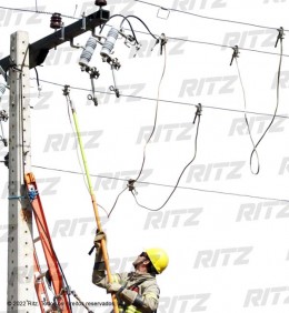
- Using the RITZGLAS® Hot Stick and proceeding as in hot line work, the phase clamps must be slowly lifted and connected to the central phase.
- Using the RITZGLAS® Hot Stick, the second and third clamps must be connected to the side phases, which concludes the phase-to-ground interconnection.
- Only after installing the grounding set, must the electrician have access to the conductors. This is to say that a line can only be deemed de-energized after being properly grounded.
NOTES
- The short-circuit current rating of the set is limited to the specified grounding and shorting cable cross-section. The cable specification may have its cross-section (mm²) and/or length changed, both to increase or to decrease it, according to the short-circuit power of the electrical system where the set will be used.
- Additionally, RITZGLAS® hot sticks can be supplied with other lengths according to operational needs. (See specific page for this product).
- The bag has reinforced edges, with internal dividers for the proper storage of hot stick sections, a carrying handle, and an additional pocket for a tool head.
